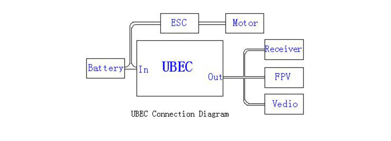
The UBEC-YL6S8A is a switching power supply type UBEC with a continuous output current of 8A. Adopting imported high-efficiency, step-down DC-DC switch IC design, small size, light weight, large output power; shielded cover, closed magnetic power inductor and magnetic ring design to avoid electromagnetic interference; also increased battery power display function Monitor the battery power during flight to avoid significant losses due to insufficient battery power and eliminate the need to add other battery monitoring equipment.
At this moment, UBEC can obtain DC voltage suitable for the operation of receivers and other equipment from 2S-6S lithium battery pack, and stably provide up to 8A output current to power devices such as receivers, gyroscopes and multiple servos. Ideal for large fixed-wing and electric helicopters. With this device, you can get the power required by the receiver directly from the power supply, without having to have a separate receiver battery pack.
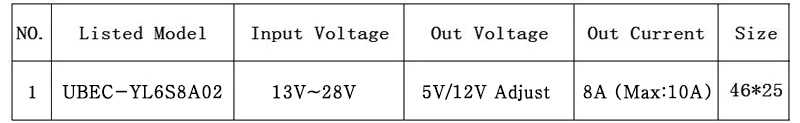
1. Product model specifications:
2, product features:
2.1, using imported buck switching power supply IC design, the efficiency is up to 90%.
2.2, while ensuring performance, the compact design, small size, light weight, only 29.5g.
2.3. Low noise design, all components are fully shielded, and closed magnetic high-power inductors are used. At the same time, the output line is equipped with a magnetic ring, which greatly reduces electromagnetic interference.
2.4, the output current is large, the continuous output current is 8A, and the peak output current is 10A, which fully guarantees the power demand of the equipment.
2.5. It has a wide range of working voltage and can work normally between 13V-28V (2S-6S Lipo) (when the input is lower than 13V, the overheating protection point is reduced, and UBEC can work).
2.6, with overheat protection, output overcurrent protection, output short circuit protection and input undervoltage protection.
2.7, output indicator, use red LED work indicator, UBEC normal working time, indicator light.
2.8, soft start switch, open or close the output of UBEC through the soft start switch.
3. How to use:3.1, UBEC-YL12S5A01: The output voltage is 5V/6V, which can be switched, and the jumper cap is used for selection. The jumper is inserted in pin1 and pin2. The two pins are selected for 6V output. The two pins inserted in pin2 and pin3 are selected for 5V output. Please refer to the figure; if the jumper cap is lost, the default output of UBEC is 5V.
3.2, UBEC-YL6S8A02: The output voltage is 5V/12V, which can be switched, and the jumper cap is used for selection. The jumper is inserted in pin1 and pin2. The two pins are 12V output. The two pins pin2 and pin3 are 5V output. Please refer to the figure. If the jumper cap is lost, the default output of UBEC is 5V.
3.3. Power indicator: The power indicator is used to display the output status. If it is bright, UBEC has a normal voltage output. If it is not lit, please check if the power input cable is connected and the battery pack is good.
3.4. Turn on/off the output: the switch is set to “ON”, the output is turned on; the “OFF” position is placed, and the output is turned off.
4. Special instructions:
4.1. Although various measures have been taken to reduce electromagnetic interference, the UBEC of the switching regulator mode cannot completely avoid a small amount of electromagnetic interference during operation; to ensure the normal operation of the receiver, please output the output magnetic ring and UBEC master Keep the distance of the board as far as possible (the magnetic ring cannot be superimposed on the main control board), and the entire UBEC should be as far away as possible from the receiver.
4.2, the positive and negative input power can not be reversed, otherwise UBEC will burn out and cannot be repaired.
4.3. When using a small number of anti-interference performance map transmission equipment, it may show that UBEC will interfere with the transmission equipment. If this happens, please reduce the number of windings on the magnetic ring or directly remove it. Magnetic ring. The main reason is that the shielding magnetic ring is used to suppress common mode interference. The more the number of turns, the stronger the suppression ability, but the larger the number of turns, the stronger the distributed capacitance. For high frequency and frequency disturbance, the smaller the distributed capacitance, the better. This distributed capacitance is also related to the material of the magnetic ring. This is why there are very few image transmission devices that may exhibit a magnetic ring and a disturbance.
Package includes:
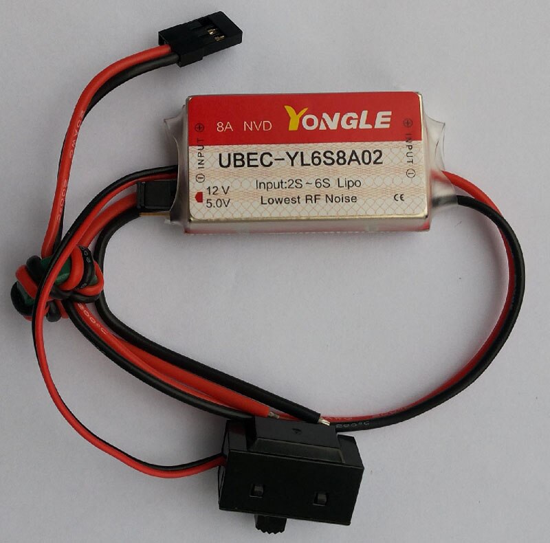
1pc x UBEC-YL6S8A02